We’re at the end of day 2 of IGVC. Things change when you really start doing tests in the field. Now the launching instructions are:
1. Put the GPS waypoints in the “GPS_Ublox/waypoints” file.
2. Run “roslaunch launch_files gps_script_node” to convert the GPS points to a useable format.
3. Run “roslaunch launch_files t1.launch” to start the robot.
I am including this here for the record.
Frank asks:
Can you give me an overview of what the nodes/launchfiles needed to run granny are?
My response:
Look at the tierX_*.launch (where X is 1, 2, 3, and 4) launch files in the launch_files package. Those are how I launched most of the nodes. Here’s a diagram that is decently up to date on nodes and topics: https://www.lucidchart.com/documents/view/4e08-7a30-515ebe1f-a2c5-0f800a0057d0
But it doens’t include Sagar’s and your lane detection. Whatever you do with vision, the binary image topic that you publish needs to be in a parameter when you run log_polar_transform. I think the name is “subtopic” or something like that. That stuff goes in tier3_vision.launch. And by the way, the launch files do not include launching usb_cam_node. For whatever reason, whenever its launched from a launch file it publishes to a different topic than “usb_cam/image_raw” so I always had to launch it outside of the launch files. You could probably figure out why that happens and fix it. The diagram and the launch files also don’t include the javascript stuff. For that to work, you have to do:
1. rosrun rosbridge_server rosbridge.py (note: this is the new version of rosbridge, in the package rosbridge_server)
2. Open a browser and go to either
a. localhost/DW if you opened the browser on doloras
b. <DoloRAS’s URL>/DW if DoloRAS is connected to the web and you’re running the browser on another computer
c. <IP address>/DW if doloras is broadcasting its own wifi network and you’re running the browser on another computer
3. Change the “ADDRESS” constant on line 16 of /var/www/DW/index.html to reflect what you’re doing (a, b, or c above)
To change goals, go into ReactiveDecisionMakers/nodes/GoalMaker.py and change the goals array. There are points that have units in meters. At the moment it just goes back and forth a ton, which I found to be useful to test.
Keep in mind that you will have to restart tier4_deciders.launch after each run. This restarts the GoalMaker (resetting the next goal) and the EKF (which may not be necessary if you’re using GPS updates, but might be a good idea to remove any accumulated error).
Lastly, I didn’t include vel_cmd_filter.py in the launch files because I used that as the “final switch” to actually start the robot moving. It’s the node that listens to the topic that javascript would publish to, so you can have everything up and running, and then finally start a run by rosrunning vel_cmd_filter. It doesn’t actually do any filtering, by the way. It used to, but it doesn’t anymore. You could instead get rid of it and have javascript publish directly to /vel_cmd, and then use PSoC_Velocities as the “final switch.”
A few things have happened in the past month. Since we’re not all in Austin together DoloRAS will likely not see much progress between now and the last few hours before the competition (although I sincerely hope that won’t be the case). Here is an unorganized mess of some thought and updates:
1. Here’s the video of us navigating autonomously outside when we were testing the EKF: http://vimeo.com/64577047
2. We have switched to using the Dynamic Window reactive technique. During the Senior Design Project open house, I noticed that Granny performed pretty badly in cluttered environments that contained obstacles other than barrels. Many of its errors (hitting things) seemed to stem from the incorrect clearance calculation it uses to evaluate gaps in the obstacles around it. So, I did some research and discovered that the Dynamic Window technique is a robust alternative. It is described in detail in a paper by Sebastian Thrun, which can be found on his website. Basically, it consists of sampling angular and linear velocities around the robot’s current state, evaluating those samples based on a series of weights, and then taking the best trajectory. I will make an additional post soon that describes several implementation details that we had to figure out and summarize the advice Joshua James gave us on the subject.
In the meantime, here is our prototype/simulation of the DW technique:
https://googledrive.com/host/0B-U60Ca9V5jnOVZWMWFMZnlReWM/test.html
3. We probably won’t be able to use the GoPro camera to stream image data because the HDMI capture device we bought does not have sufficient Linux support. If it were the beginning of the semester, we might be ambitious enough to write our own drivers, but unfortunately it is not the beginning of the semester and we are out of time and out of money to buy an additional capture card. This is a huge bummer, because for a good part of this semester we had be blaming the poor output of our image processing code on the quality of our webcam.
4. The realization that we will probably have to stick with our current webcam, coupled with the fact that we are quickly running out of time, has led us to make a lot of progress in vision. In particular, Frank and Sagar have been hard at work on two new nodes, one to threshold images based on red, blue, green, hue, saturation, and value, and one to run Hough line detection. Their efforts seem to be fruitful. One important step they made was to create a GUI to easily find the best thresholds for certain obstacles.
5. Cruz has been working on getting the EnterpRAS up and running, which would be really great since it has an Intel i5 processor, capable of handling a larger load than the Intel Atom processor that DoloRAS uses. Unfortunately, it seems likely that he will not be able to finish getting everything up and running before the competition.
6. Just before I left for the summer a week and a half ago, I was able to briefly test our DW implementation using our vision pipeline on a simplified environment. It seemed to perform as I would expect. I wanted to eliminate errors induced from any other system, so I went to the 3rd floor of ENS and only used lane detection with our white planks (so as not to induce any errors from lighting conditions) to generate obstacle-avoidance scans. Here is a video of that:
<video I will eventually upload>
7. Unfortunately, I didn’t have time before I left to give the code memory, so it is still purely reactive, making decisions only on the most current scan. This means that Granny is likely to hit obstacles or run over lanes that have sharp corners, since they will end up being out of its field of view. We had not focused on this problem, since we assumed that we would be able to use the GoPro, which has a 180 degree view (as opposed to the webcam, which has a 30-40 degree viewing angle). It turns out that depending on something that hasn’t been seen to work is a bad idea.
8. One major implementation choice we made having to do with the DW code was to run it in Javascript in a browser, rather than as a node in ROS. This is partly because of my recent obsession with using Javascript. It also has to do with the fact that Cruz will probably not be able to get our code on EnterpRAS working, so we need to be able to offload as much processing as possible (much of our vision code has been offloaded to the GPU using OpenCV’s CUDA support). By using a package called rosbridge, and a Javascript library of the same name, we can enable a Javascript client to subscribe and publish to topics, as well as interface to services running on DoloRAS.
This means that rather than running the DW code in a browser on DoloRAS, we can connect another computer over the network and use its browser to run the code. Which computer we use doesn’t matter. It just needs to be able to connect to DoloRAS over a network, and have a browser–nothing else is required. Just before I left, I unified all of the services that the DataServiceProvider node provides, making it only necessary to make one service call to obtain all of the most recent data. I wasn’t able to directly measure the latency after I made that change, but I did observe the decision loop publishing back to DoloRAS at around 40 Hz, which is certainly sufficient.
Personally, I think this method of using a browser to control our robot is really quite cute. It has numerous benefits. It makes absolutely no assumptions about the computer connected. For example, we could use a laptop that can run off of its own power. If one laptop dies, we can replace it with another very quickly. Another benefit is that our prototype code (in the demo I linked to above) and the code that actually makes the robot move is exactly the same. This benefit would also come if we had ever gotten VREP or Gazebo integrated with our code. It also makes visualization easy. From our experience, graphics libraries in Python or graphing tools in ROS incur an unpleasant amount of load on the system. However, depicting data in a browser is easy, and most modern browsers optimize graphics on the HTML5 canvas. By offloading the DW code to an external browser, we can afford to render a verbose, realtime depiction of the decision-making process.
9. We’ve started to use the Hokuyo range finder again. Chris H. took it apart a little while ago to see what was inside, and when he put it back together and plugged it in, it worked on the first try. It’s still being temperamental, but I think it might just last until the competition. I have become very frustrated with the sonar array because of the noise it induces into the system. (See a relavent note in the “Things to do next year” page.)
10. Our IGVC design doc is here:
https://docs.google.com/document/d/1DESwco5fg9WB3DKzQ51f1nYTJshM9ttxalOdC05EGjQ/edit
We bagged data of autonomously navigating to three GPS waypoints this past Friday. To better understand how our EKF implementation performs, we ran several EKFs offline at the same time, and had them listen to different combinations of the updates being played back in the bagged data.

This is a plot of the raw GPS data we collected, plotted using the Google Maps API. In reality, the robot drove practically straight to each waypoint, wavering slightly.
All of the charts below were drawn in a browser using Javascript to render on HTML5 canvases. You may question the process here, asking “Oh God why would you use Javascript?” The answer to this is that we had to use a browser anyway in order to use the Google Maps API, as seen above. So, why not use rosbridge to expose ROS topics to the network, listen to the Kalman filter updates along with raw GPS data, and plot them along side each other in real time?! In addition, we’ve found that using mjpeg_server in ROS and displaying mjpegs on client webpages is a much better way of viewing live camera data than X-forwarding the image_view ROS node window. Also, I really like Javascript.
By using the browser to display data, we can view stuff streaming from the robot to a web portal without requiring an SSH session, and enable it to be viewed from anywhere in the world. Even India, for example! Which is surprisingly relevant, since it appears that this blog has gotten more hits from there than anywhere else in the world combined.
NOTES ON THE CHARTS: each point plotted below uses a colored circular point and a white line stemming from the point to indicate direction. The points and white lines are plotted one on top of the other. The hue of the circles vary with time, so since there are so many points, the charts appear to display smooth psychedelic transitions of the rainbow. Each square on the charts are 4 by 4 meters wide.
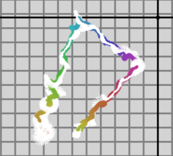
Chart 1: This is the EKF’s output given only the processed GPS data. By “processed data” I mean the raw data converted to x/y meters, using an arbitrary GPS location near by as an origin. No other filtering is applied.
Notice that in the plot above, the Kalman filter does a miserable job of tracking the robot’s heading, especially at the beginning. We believe that this is valid behavior, since the filter could easily explain our scattered position updates by believing that the robot was moving backwards and spiraling, having no angular or linear velocity updates to think otherwise. When the robot isn’t moving on the x-y plane, the EKF is left to believe whatever it would like about which direction the robot is facing, since it has no information on the subject.
When combined with the encoders, which we use to get angular and linear velocity updates, the plot (Chart 2) is much cleaner. We used these updates to the EKF when the robot took this path autonomously:

Chart 2: This is the EKF plot using GPS x/y updates plus encoder angular/linear velocity updates.
What’s really nice about Chart 2 is that it shows reasonably estimates of direction without using an IMU. This means that if the power generators at the competition introduce errors in the magnetometer which cannot be compensated for, we’ll still be okay. However, if we use compass updates that are not erroneous, rather than encoders, we get something a lot smoother:

Chart 3: EKF output using GPS updates plus the IMU’s yaw updates
The plots above use GPS to globally localize. Not using a global position update would lead to the EKF’s position estimate to incur error over time and drift. Similarly, use of the IMU’s yaw value can give us a global heading update. As seen in chart 2 above, without global directional updates, the EKF can still estimate global heading by using global position updates. (As if it were connecting dots and noting then observing the direction of the connecting line.)
It would be interesting to see what happens without either global position or orientation updates. Updates from the encoders come in the form of position and orientation derivatives: linear and angular velocities, which are based on the robot’s initial reference frame, not the global reference frame. Using only these updates, we would expect quite a bit of drift with both direction and position, because any slippage in sliding of the wheels would cause erroneous [non-Gaussian, mind you!] updates. However, it turns out that it isn’t so bad, as you can see in Chart 4:

Chart 4: EKF output using encoders only
In fact, it looks pretty good! The drift appears to be small (within 2 meters). In reality, we probably just got lucky. If the wheels had slipped at all on the field, we would not be seeing such pretty data–in the past, we have seen slippage mess this plot up quite a bit. Notice that the path above starts at the origin since the EKF initialized with a (0,0) position, and there is no global position update to tell it otherwise. The path also appears to be rotated from the other plots. This is because the EKF is initialized with a direction of 0 radians, and there is no global orientation update to tell it otherwise.
We observe some odd behavior when including a global directional update with the encoders (again lacking GPS updates). It appears that there is more positional drift with orientation updates than without, as you can see here in Chart 5:

Chart 5: EKF output with only encoders and IMU orientation updates
We’re still trying to explain this. It could have something to do with the fact that the yaw update appears to be slightly offset by about 10 degrees counter-clockwise, as can be seen with comparing this to the raw GPS data given at the top of this post.
Despite this, we can bask in the beauty of combining all updates into one, cohesive, glorious state estimation, which appears to be qualitatively reasonable:

Chart 6: EKF output using encoders, GPS, and IMU orientation updates
Some recent developments:
1. Cruz, Sagar, and I had the opportunity to test the robot out on the intramural fields on Friday. After some work, the robot was able to autonomously navigate to three GPS waypoints while avoiding traffic barrels. We used the encoders and GPS updates to localize, and the sonar array to avoid obstacles. It seemed to be able to get within a meter of each waypoint, which was better than we were expecting.
We chose not to use yaw updates from the VN 200 IMU since there was a small reference conflict that we didn’t have time to fix on the field. Yaw=0 indicates that the VN 200 is pointing north (so the x-axis of the global reference frame is positive in the north direction). This conflicts with updates from the GPS offset node, which is (x, y) pairs where positive y is in the north direction. This has since been fixed.
Despite not having yaw updates, the EKF was able to accurately estimate its direction after moving for a bit and seeing updates from the GPS sensor. It took a few seconds of driving in the wrong direction, but it got it eventually without any help. This gives us confidence that at the competition we won’t have to rely too heavily on our compass. Magnetometers are known to have issues on the field due to the generators they use to provide power. I will make another post detailing EKF results with pretty charts.
From the data we collected with white lanes from the intramural fields, it seems we have some work to do in lane detection. Actual painted lines are a lot more difficult to detect than the boards we were using to test with last week. Sagar is experimenting with different gray scaling techniques to make the lines stand out better.
2. It turns out that our sonar array is suffering from a couple of issues. First, the calibration image shown last post is in fact evidence of “cross-talk” between the sensors. It cannot easily be accounted for. Also, we’ve found that the gap between sensors is too large, causing some large blind spots. This is especially a problem with the tall, thin cones, which it can sometimes run into. It works for large obstacle avoidance, but it is far too noisy and inaccurate to be used for mapping. I’ve sent emails to a few companies that sell Hokuyo and SICK laser finders to see if we can get another product donation.
3. The PSoC-Computer connection has become much more robust. Frank added a diode to the power distribution circuit, which appears to be preventing the surge we were observing before. He also has the PSoC’s fault handler reset it, so if other hard faults come up they won’t cause the whole system to go down–things will only pause for a second or so. PSoC_Listener has also gotten better. We’re trying to migrate all of our drivers to not crash if they momentarily loose connection to their sensors, and instead wait for them to reconnect.
4. We’ve decided to try to have both the EnterpRAS (a computer we used the last time RAS competed at IGVC) and DoloRAS (our current computer using the Atom processor) on the robot at the same time. Reasons for added the EnterpRAS are that it can fit the Quadro GPU and the HDMI capture card, and its i5 processor is faster than our Atom. A reason for keeping DoloRAS is that Intel has given us $3000 for this project in order that we use their Atom processor. Hopefully the power draw won’t be too much, and we can communicate between the two computers easily with ROS.
We’re continuing to try and push forward to complete as much as we can before open house next Wednesday. Lucas has made some progress on characterizing the carpet of the third floor:


I’ve been working on cross-calibrating the Sonar array scan and the binary image scan in order to make each more reliable:

Image taken with a large white board standing vertically approximately a meter away from the front of the robot

The tick marks on the axis indicate meters. Dark blue: uncalibrated sonar scan; light blue: calibrated sonar scan; green: scaled image scan; red: calibrated image scan
Note the warping of the sonar scan above: even though the robot is facing a flat surface, the sonar array would have us believe the surface was curved around the front of the robot. This is likely a result of some kind of interference between adjacent sensors.
Other various news:
- Things on the hardware list are slowly being ticked off
- We will likely be receiving a product donation from Trimble in the form of a GPS sensor which is compatible with OmniSTAR! I got a friendly call from one of their representatives a couple of days ago requesting our shipping address.
- The Quadro 6000 GPU that NVidia promised to donate us should be coming in either this week or the next.
- One of our twelve sonar sensors was confirmed dead late last night. This cause of death is as yet unclear. It was possibly linked to our lack of a protective bumper in front of the robot, allowing sensors to occasionally smash into things while testing. A pool noodle/PCB enforced bumper is the highest-priority item on the hardware to-do list. It could also have been linked to a surge problem we have been observing when the remote kill switch is hit. Frank believes that the solution to this surge issue is to decouple the PSoC from the computer, using an Ethernet connection rather than USB.
- Andrew has made excellent progress on getting V-REP up and running. We expect to have it integrated into our setup by the end of next week, at the latest. We hope to use it to run the robot through the basic and advanced courses.
Separate from running autonomously on the 3rd floor, Sagar has been working on getting white lane detection working outside. His current strategy is to blur the image, grayscale it, run Canny edge detection, and then send it through a Hough transform. He was able to get all of this done on our GPU, except for the Hough transform. One innovation he made is to run an HSV threshold on the original image to detect whiteness, dilate those pixels in the image that passed the threshold, and then do an AND operation between the thresholded binary image and the gray scaled image that was processed with Canny edge detection, just before running it through the Hough transform. The reasoning for this is that it gets rid of edges that are not apart of the more relevant, white areas of the image. Shown below are his initial results from data we recorded with white planks of wood on the ground. (All of our previously bagged data with actual white painted lines was recently lost due to file corruption on the external harddrive we were using to store bags. We felt it wouldn’t be wise to paint the lawn beside ENS without permission.)


Lines drawn from the Hough transform are shown in blue
Note that the image above was not taken with actual white painted lines, and it was a cloudy day, so the whiteness of the lanes is probably stronger than in reality and the lighting of the image is generally favorable. This is particularly relevant because of the notorious “barrel” problem cited in many an old IGVC design doc. It seems that the color on the reflective strips of construction barrels is indistinguishable from the color of the lanes. We hope to get some bags at the intramural fields either today or Friday in order to test with more realistic data.
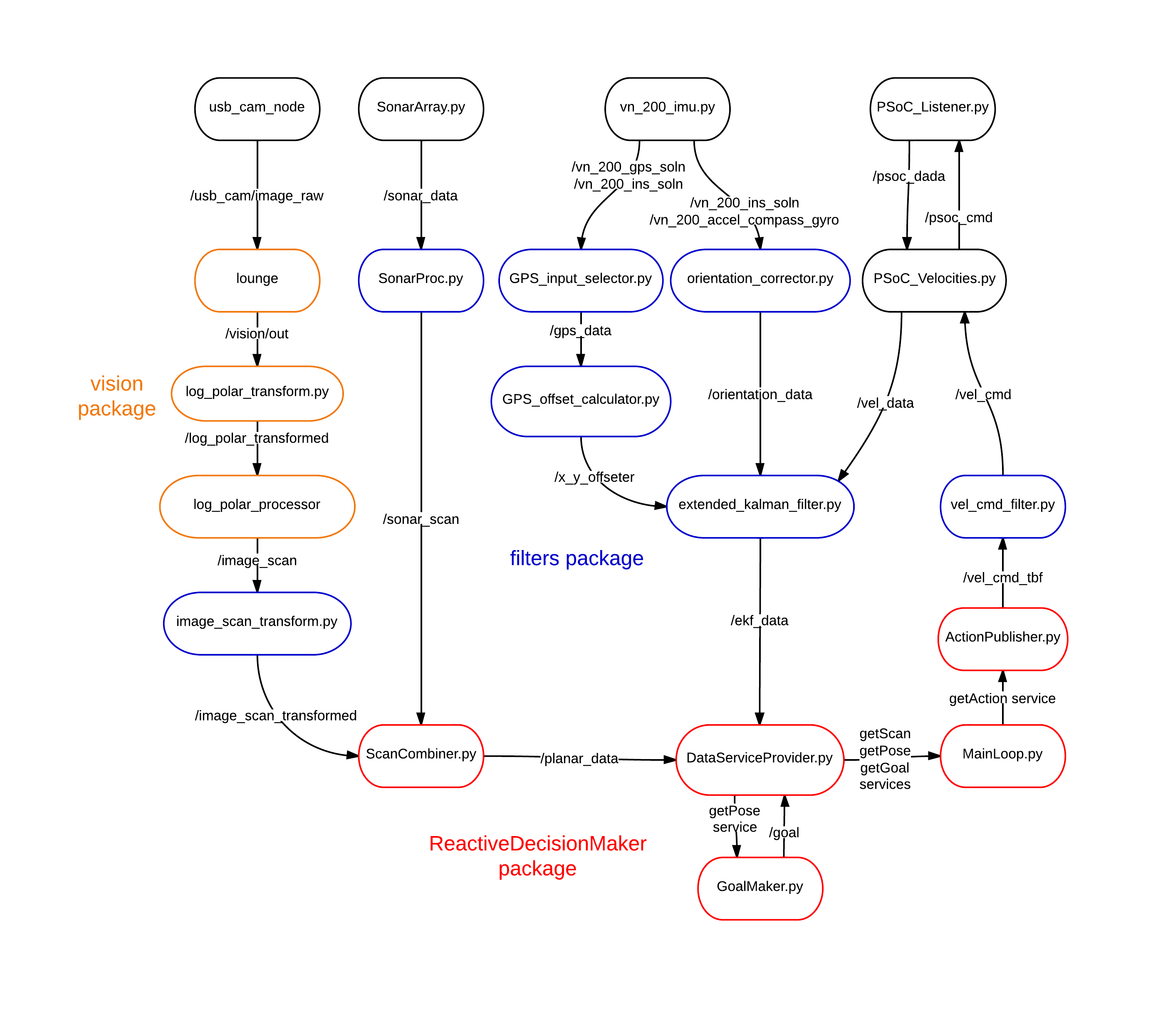
The Senior Design Project open house in on April 24th. We will be presenting on the third floor lounge of ENS, so we thought it would be cool if we had the robot autonomously navigating around people during the event. Here’s is an updated diagram of the nodes, topics, and services that currently run as we test navigation:
Navigating around people and other objects is trivial if the sonar array is working properly. However, we believe that it would be more impressive if we did this task exclusively using vision processing. In order to navigate around people using vision we’ll have to try a different approach than the one we’ve been using. Rather than characterizing the HSV thresholds of obstacles, we will characterize the floor, and treat everything that does not look like the floor to be an obstacle. We are lucky in that we will have 24 hour access to the place where our booth will be, so we will be able to easily test and develop in the coming days.
From recent testing we have discovered an issue with the PSoC’s connection to the computer. Occasionally the PSoC disconnects when the remote kill switch is hit. We also have observed the power supply to the computer turning off when it is being powered from the wall and the kill switch is hit. This problem could stem from the fact that everything in the system is on the same ground, and a spike could occur when the power is cut to the motors (even though our motor controllers should protect against this). Our current solution to this is to decouple to PSoC from the computer by using Ethernet to pipe data instead of USB. If we do that and then power the monitor and computer with a separate battery, the computer and components powered by the computer will be completely decoupled from the motors and batteries that power the motors.
In other news, we have making a few purchases. Since the VN 200 does not support either OmniSTAR or WAAS, we have bought a GlobalSat BU-353 GPS receiver, which has WAAS support. We have also bought a HDMI capture device which we expect will be able to allow the Hero3 to stream images. In addition, we’ve been trying to acquire as many duplicates of parts as possible so that no single component of our robot can fail the day of the competition without us being able to replace it.
Chris H. has started to work on using PTAM to give our EKF another source of odometry. There appears to be issues with finding features, and it may become a CPU hog. However, it may also prove to be a good source of error correction in case we slip on grass and our magnetometer gets screwed over by IGVC’s power generators.
Here’s some details on recent events.
Last week we received a product donation from GoPro: a Hero 3 camera (Black Edition). Some of its notable features are the “ultra” wide angle lens, water-proof case, and attachable lenses. Unfortunately, there doesn’t seem to be much support for streaming pictures over USB, or much of anything for Linux. All we’ve been able to do so far is stream it to GoPro’s iPhone app and take pictures and video using a Micro SD card. Since the camera is set up to stream over HDMI, our current plan is to get an HDMI capture device and plug it into our PCI Express slot. We’re currently in the process of contacting companies that sell HDMI capture devices, since we’re pretty much out of money at this point.
We finished some initial work on getting the sonar array publishing into the system–a node has been created to act as a driver for an Arduino Omega board that is connected to the 12 sonars. I’m not sure if I’ve explained our reason for using a sonar array explicitly. We conceived of the idea originally when the Hokuyo started to malfunction, so we already had a plan to execute when it finally died. Inspired by what RAS did for IGVC in 2009, we have connected a bunch of sonar sensors together in a half-ring. There were about $3 each, but are actually supposed to be pretty good. The data isn’t scaled properly at the moment, so we haven’t been able to bag anything to analyze yet. Here’s a picture of the sonar array taken with the GoPro:

The VN 200 does not have support for OmniSTAR’s subscription service. The GPS data we’re getting back from it is accurate to within 5 meters when staying still, and about 2 meters when moving, but this will probably not be good enough. The competition requires that we reach waypoints within 2 meters. So, we’ve begun to contact different companies that produce GPS receivers that are explicitly compatible with OmniSTAR to see if we can get another product donation.
We’ve also been able to analyze the results of using messages from the VN 200 Inertial Navigation System (INS) in our Extended Kalman Filter (EKF). Unfortunately, from looking at some data we recorded the other day at the intramural fields, our EKF’s orientation estimates are better when ignoring these INS messages and instead working directly with the accelerometer and magnetometer messages (even with proper covariances for each). The INS yaw value appears to drift over time, whereas from using our calculations of roll, pitch, and yaw (using this as a reference), we do not observe any drift. We have not yet done any hard & soft iron calibration.
This weekend we hope to be able to go back to the intramural fields to see if we can autonomously navigate to GPS waypoints using both the sonar array and the camera. This would be a big milestone for us, since all we’ve done so far is navigate to local waypoints around obstacles using only the encoders (feedback from the wheels) as input to the EKF for localization. We haven’t ever navigated to actual GPS waypoints before, and we haven’t done anything autonomously while incorporating GPS and IMU sensors. Using the Hokuyo, the robot was able to navigate around obstacles very well; the same code run with the camera has proved decent, but it still scrapes the edges of orange obstacles. Integration of the sonar array scans and the camera image scans remains as yet untested and there’s still some work that needs to be done for it to work. So, it would be a huge step forward if we’re able to observe robust navigation with all these different components running at once.
Here is a dataflow diagram with the nodes that are currently running in the system:

click to view data flow
By the way, we’ve got 59 days before the competition!
Discussed:
* V-REP
– Installed on granny, needs ROS integration
* Hareware stuff
– A few things were finished (see spreadsheet), but still needs a lot of work
* Sonar array
– Cruz working on driver for Linux
* Vision
– Lucas: still no progress
– Orange filters need some work, see the “barrels_cones_4-5-13_*” bags
* Camera
– Can take a video with micro SD card and view it on a computer
– Can’t stream
* VN 200
– Now integrated with EKF
– Initial tests show that GPS is disappointing (see this report for more details)
– Emailed VectorNav about OmniSTAR compatibility
* PATW competition on the 27th
– Cancel it. Instead, we’ll go to A&M the next weekend to test, as practice for going to Michigan
* Sparkfun competition in Boulder, Colorado
– Wth, it only costs $30 to enter. Letths get em.
To do:
* Acquire tall orange cones
* Get micro SD cord and HDMI recorder
* Test VN 200 in an open field
* Hareware stuff!!!!!!!!1111
* Get a GPS receiver that is compatible with OmniSTAR
We have been testing in the past few days, and some things have come up. Here are some updates/comments relating to them:
1. Running PSoC_Listener after restarting the computer always fails on the first time, and must be restart. Here is what’s displayed on the console:
[INFO] [WallTime: 1365072413.598298] PSoC Listener is running on /dev/PSoC
[INFO] [WallTime: 1365072413.609293] Info message from PSoC: INVALID START CHARACTER:
2. On the walkway the robot can only make it over the ramp if it goes at around max speed. It might be easier to do this on grass. It also has issues trying to make it up the hill between RLM and ENS, but this is due to it slipping on the wet grass.
3. The remote kill switch is ON if it doesn’t have power. This means that if the remote kill switch gets unplugged or dies, the robot could go charging forward, and the only way to stop it will be to hit the emergency stop. Speaking of which…
4. The emergency stop is still mounted on the front of the robot. This makes the situation of the robot getting out of control even more fun!
5. The vision scanning now can go at a comfortable 10 Hz. Our robot can navigate autonomously around red/orange things using only the camera. However, since the decision making code is still reactive, it sometimes hits cones when they drop below the view of the camera.
6. We really need to have fences and colored drums to test with.
7. We’re blocked on:
-
No bagged VN 200 INS data to test EKF integration. Apparently it won’t publish INS data without a GPS lock, and we haven’t been able to get a lock around ENS.
-
No sonar driver written for Granny yet. The sonar array also needs to be mounted.
-
No driver yet for the GoPro camera.
8. We really need to mount the monitor. We also need to mount the power converter for it.
9. I added a page to the wiki on GitHub describing the reactive decision making nodes. We should add more pages on that wiki that describe other sets of nodes and parts of the project. It would be good to have a single place for all documentation.
